Showing posts with label howto. Show all posts

Tuesday, April 24, 2018

Basement-Engineered Home Brewing Stirplate


Although my outdated, neglected, who-gives-a-shit blog rarely gets posted to anymore, I have adopted a soft spot in occasionally 'giving back' and sharing to a focused community of DIY folks, especially in the home brewing world.  This happens to be one of those moments.

I've been a very in-tune and serious-to-the-hobby home brewer for just over 3.5 years now.  Much like anyone starting out, there is a metric ton of learning and process fine-tuning involved at a serious level, well beyond just making a remotely drinkable extract home brew.  On top of that, it's a fucking money pit like any other hobby, but it also is the most collaborative and knowledge-sharing thing I've ever been a part of.  From the just-starting-out brewer up to a seasoned Brewmaster at a brewery, anyone will talk 'shop' with you, give you pointers, and help you along the way.  

For me, when cost-meets-process come into play, some will gladly pay for their home brewing solutions, while others try to DIY and/or re-invent the fuck out of the 'wheel of everything'.  I feel like I'm right on the fence and just depends on my mood, ambition and if I feel like exerting my talent and time vs. making my checkbook a bit lighter out of pure convenience.

So what the fuck is this all about?  It's about yeast cell generation and using a stirplate to perfect it.

I've always made 'shake when you walk by' non-stirplate yeast starters for years, and although many of the online tools for cell growth and propagation are slightly better-than-ballpark accurate, I felt like it was one of those core pieces of the brewing process I needed to improve to make/create a better fermented and consumable product, if not for any other reason, than for my own self preservation... and my kegerator.

In regards to stirplate topics as a whole, seems like most of us toying with this piece of equipment either have something already they aren't happy with, are in the market for one or simply not using one at all.  Let's take the upper and lower extremes of these camps:
  • Purchasing a $120+ Maelstrom stirplate from NB.  Some of us have disposable income to waste.  I don't know a single person in our home brewing community who owns that thing except for one person a friend of mine knows.  
  • 12v PC fan with a random potentiometer hack off a voltage regular.  Mechanically and from an engineering point-of-view (I don't care how pretentious I come across as) --- not a real solution.  Not to mention, it's shitty internet sheep plagiarism.
  • Legit, used lab-grade stirplate off an auction website.  This falls into the buy-it-the-fuck-already club.  If there's anything I would respect and trust the most, it's this.  But depending on the 'used' factor of this, it's not entirely out of the realm of getting a dud.
  • Buy a Stirplate kit.  There is but 1 or 2 real-deal engineered solder-yourself solutions I stumbled upon.  One of which was archived and you couldn't buy it, the others were PC fan knock offs. However, it's just the kit --- you need to find the proper enclosure and rest of that jazz.
  • Stirplate is you.  As mentioned above and how I was doing all of this.  I know friends who still do nothing more than agitate their still yeast starter over a period of 1-2 days when they walk by it and make way better beers than me.  Absolutely legit.
But whatever avenue you go with, it's the same problems:
  • They throw stir bars and often.
  • Linear variation in speed control is way more powerful than they need to be to make a vortex to draw in oxygen into wort solution while keeping yeast in suspension, but all the while, you still need that balanced power when considering, for instance, very large starters in 5000ml flasks.
  • The variable sweep of the speed you can dial for stirring (if that option exists) is not smooth and linear; it's pretty much on, slightly spinning or straight to 80,000,000,000 mph in a clockwise range of 6 to 3.
  • Some stirplates are under powered in the current department (if ran by batteries) so good luck making the minimum ~24h to double yeast cell rates because the draw off the DC motor will murder your battery in no time and you'll walk by a stirplate that isn't stirring anymore.
  • In regards to the stirplate being all about you, is that you get tired of babysitting that thing, forget to shake it, etc.
I like difficult problems and after pealing this back, and believe it or not:  This wasn't the easiest problem to solve, let alone, solve correctly.

Now let's say you settled on making one yourself like I did.  One thing I can attest to up front:  for pure reference material, there is but maybe 2 or 3 legitimate pieces of content that even talk about electrical engineered home built stirplates on the ENTIRE internet.  I've looked.  And looked.  And looked.  I can't even find a good boilerplate schematic or circuit to work off of or get an idea going from.  And anything I did find, I knew after 5 seconds of looking at it, there was no way that was working at all.

I think the biggest hurdle is turning all that Earth science and physics into a real electrical engineered solution.  Even though this is NOT my wheelhouse what-so-ever, and I'm a mere hack EE hobbyist, I'm not naive to any of these things below that really mattered WAY more than engineering the right circuit design and parts IMHO:
  • Magnetic field strength over distance to the non-competing polar magnetic source (e.g. stir bar) matters.  
  • Increasing magnetic field strength with lower to super strong magnets and stacking and finding the right balance that balances well with gravity, water mass, the magnets in your stir-bar, while not adding too much torque stress on your motor.
  • The diminished effectiveness of magnetic pull between different layered materials such as pyrex, plastics, glass, whatever.
  • Centrifugal force in relation to the stacking, mounting and centering of the magnets over the shaft of the motor unit doing the spinning.
  • Calculating the proper duty cycle for the DC motor involved in the design so it receives the correct amount of 'kicks' (pulses) over a variable range that's seemingly very focused and linear.
  • Housing material for the stirplate itself can't compete or interfere with the magnets to be durable, waterproof, hold a flask of 2000ml or larger, and clearly, house the design footprint as well.
  • Gravity and mass of different volume levels of water and it's effect on stir bar (e.g. holding it down in relation to weight of the water and gravity over it), the increased torque on the motor that is needed to overcome and 'spin through it'.
  • Not lose sight of the fact that this thing needs to do what it was made for:  agitate a solution with some spinning object, make a small vortex in liquid to pull in oxygen and do that task over and over for a long time.  Basically:  solve the problem without over-engineering the shit out of it.
I'm sure there's much more to say, and better eloquently put, too.  But you get the point I'm trying to get across:  there's a lot to consider and work through if you want to solve those problems above.

Without further ado, after almost 3 solid months of basement R&D, ripping shit off breadboards and starting completely over countless times, re-education in all that wonderful high-school level foundations in physics and Earth science that we all forgot eons ago, I bring you:  a legit, working stirplate.


The Schematic


Best part about this (to me) is it's a complete hardware PWM solution, 100% portable and reproducible.  I'm very comfortable and skilled with AVR microcontroller development, but implementing a timer based PWM solution to create a duty cycle I can calculate already with some math on a 555 timer is a way easier re-build for anyone else who wants to create this.

In the schematic, you'll see the use of an AVR, but it's just to use ADC to read the linear analog pot sweep that speeds/slow the duty cycle to the motor via the H-bridge IC and light up the LEDs in a seemingly eye-candy sort of way; it's totally optional and does nothing more than provide a visual reference of 'speed' beyond the potentiometer knob. Everything to the right of the dotted line "you need" to make this work. Everything to the left (e.g. AVR + LEDs), you don't.


The Parts List


Some quick notes on the parts list. I had a hard time generating + exporting one with KiCad , so it's easier to just jot down some specifics of some of the parts that maybe need some explanation.  ALSO, get the parts where you want.  I'm listing where I got it, but I order from Amazon, Sparkfun, Adafruit, Jameco, Solar Robotics, and a handful of other places.


  • Sparkfun Hobby motor:  I bought a handful of these for a solar-powered motorized steampunk garden robotic project I was working on and had them lying around.  The design lesson is:  Don't go beyond the 3v boundary to drive these for a stirplate.  Even though Sparkfun says "up to 12v", don't.  From a current perspective, thing seems to need to sync about 450-500ma just to get going @ 3v.
  • SN754410 H-bridge:  I initially went down the path of trying to procure a L293D, but this was cheaper and was like-for-like on pinout.  But it's output current is 1A.  Yes, there are 'other' H-bridge ICs out there, but remember you need at least 500ma for that motor to start.  That's why it was chosen.
  • 5v VCC source:  I have a ton of old flip and pre-smart cell phone chargers around from my every-year-free-phone upgrades of the old days.  Just pick something that's 5 volt DC and at least 850ma or higher.  1A preferable if you're going to use LEDs and microcontroller.
  • LD1117V33 voltage regulator:  Absolutely essential for driving the motor voltage source on the SN754410.  Running the motor at 5v is too much; the more voltage, the higher the RPMs. However, you still need source 5v for the VCC power requirement of the 555 timer and the SN754410.  I reference this, but I happened to have the older LD33V around that I used, but same thing.
  • 555 timer:  As opposed to doing any PWM and duty cycle calculations with the AVR (which you can), I wanted to keep the stirplate as 'hardware' as possible.  But see diode notes below this; the 50% duty cycle was just too much and I had to figure out a way to get lower than that.
  • 1N4148 diode:  This was the crucial component.  With a 555 timer, at best you can get 50% duty cycle with R1/R2 resistors.  You can get lower if you put a diode across the pins.  Since you're powering it with 5v, use the 1N4148.  This calculator was invaluable as well in enlightening me towards that path.
  • 1k Linear Pot:  I used linear because I wanted it as smooth as possible.  Unfortunately, I bought a super cheap Chinese potentiometer to save project costs and the sweep rate sucks on it.  If you wanted to spend more money on a higher quality trimmer pot with more precise turn counts, do it.  It'll only make it better, smoother and dial in speeds better.  Don't do logrithmic --- you won't be happy and the growth ratios of speed up will NOT be what you want; you'll go from 0 to 80,000,000,000 mph as mentioned above.
  • 5"x5"x4" enclosure:  I am glad that I happen to stumble upon this on Amazon.  This worked out great and sized well with the array of Erlenmeyer flasks my friend let me borrow for testing.  It's got a gasket on it for water-proofing, it's light but the plastic is super durable.  Plus, the lid depth is not flush with the top of the enclosure, so it was easy to 'build up' magnets and the motor mount bracket to get just right.
  • Ceramic Magnets:  I used a combination of low-power and high-power magnets as explained above. I got mine at Lowes, but I'm sure whatever home improvement or hardware store has something similar.  I used them as my base magnets because they had a bit more height than just using a rare earth or high-power magnet out of a spinning disk hard drive.  There is a picture of this.
  • Hard Drive (neodymium) Magnet:  You totally need this, too, but just one of the two that you usually get when you tear open an old hard drive to get one.  Just go find an old hard drive from a half-rate PC repair place in your city/town or if you have 8,000 sitting around like I do. And if you're really clueless, watch a Youtube video how to get it out vs. brute forcing it like a cave man.
  • Stirplate Bar for Magnets:  This is just a 3" zinc mending plate I bought at a Menards or Lowes.  I drilled into the center and just wedged it onto the motor shaft.  Don't remember the drill bit diameter, but whatever the shaft was, I just got it 'right' so it snugged right on.  Then the ceramic magnets were stacked correctly and epoxied on.  The weight of this in combination with the magnets is 'about' right for the physics side of keeping the spinning smooth in check.
  • Motor mount:  That's just a 1/2" electrical conduit shaft thing I found in some junk pile in our datacenter at work that was being thrown out.  The hobby motor perfectly fit in there.  Then I just bought an "L" bracket and screwed it on and epoxied it as 90 degrees and straight as possible for extra stability.  The motor can come out though --- remember if it burns out, I just want to replace the motor, not remake that whole thing again.
The optional parts (for the LED eye-candy):

  • ATMega168:  AVRs are my microcontroller of choice.  I don't even use the Ardunio frameworks; just straight avr-gcc as my compiler.  I could have used an ATtiny or something, but I want to ditch the LEDs and put on a 16x2 character display instead.  So if I need to add it, I've already got the microcontroller with ample GPIO port pins to handle it, and it's a batter of just cutting out the display space on the enclosure and soldering it in.  But whatever AVR you pick:  you need at least 6 free GPIO pins for LEDs and it has to do ADC conversion to read the analog pot value and convert it to digital.
  • LEDs:  Some grab-bag shit I have around.  I just picked colors of blue, the middle was yellow/green and the last one was red.  I just put in nominal resistor values for blue and red because they were a touch brighter than my yellow/green ones, even though the voltage drop on those tells you otherwise. Don't read too much into that --- I just wanted the brightness to be visually 'even' between LEDs.
  • IC DIP sockets:  For the love of all things engineering, please solder in IC sockets in case you kill an IC or whatever, you pop it out vs. soldering it directly to your thru-hole board.  We're talking mere pocket change here.  I can remove the 555-timer, H-bridge or AVR (or upgrade them), especially the AVR; you'll be able to take it out, put it on your development board, write your new sketch, and pop it back in.  

AVR Code/sketch for ADC + LEDs


Honestly, there isn't much to this.  I spent way too much time monkeying around with ADC converted values from my pot, trying to create a fill-value map range just so it gave you a nice, visual "cute and smooth" light up pattern.

Going back to my crappy Chinese potentiometer, a lot had to do with it's cheapness.  I ended up taking up to 150 samples triggered off ADC interrupt, totalling and finding the mean, then creating a smaller linear map number value range.

Here's what my ADC Interrupt routine looks like:

ISR (ADC_vect)
 {
   trigger++;

   if ( trigger < 150 ) {
      ADCvalue += ADCH;
   } else {
      uint16_t mean;

      mean = ADCValue / (trigger - 1);

      sweep = map(mean, 0, 195, 4, 58);

      ADCvalue = ADCH;
      trigger = 1;
   }
 }
Then in the main() loop, I just check the volatile global value of the ADC sample average of that window and have the LEDs turn on as the potentiometer value increases:
while (1)
 {
    if ( sweet >= 67 ) {
       // turn on all LEDs, adding final RED
    } else if ( sweep >= 45 ) {
       // Add in final Green/Yellow LED
    } else if ( sweep >= 26 ) {
       // Add in middle Green/Yellow LED
    } else if ( sweep >= 14 ) {
       // Add in first Green/Yellow LED
    } else if ( sweep >= 12 ) {
       // Add Green-only LED
    } else if ( sweep >= 10 ) {
       // Just Blue LED
    } else if ( sweep >= 9 ) {
       // Just Blue LED
    } else {
       // NO LEDs
    }

    _delay_ms(200);
 }
If you were to graph those values, they aren't exactly 'linear' either and look more exponential, but do notice how the values sit low then suddenly, it changes, and I'll chalk that naively (again) to using a cheaper grade potentiometer.  My sweep really looked like this:


So even my map() function to convert on linear range to another smaller linear range wasn't evenly divisible at all, in terms of using the 'clock face' analogy that if your mapped range is 0 -60, dial is at 6 o'clock that 0, noon/12 o'clock should be 30 and almost back to 5/6 o'clock again would be 60; that's not the case.  So I just played with the numbers until I felt it looked right when moving the knob from 'off' to 'full throttle':


long map(long x, long in_min, long in_max, long out_min, long out_max)
 {
    return (x - in_min) * (out_max - out_min) / (in_max - in_min) + out_min;
 }


All that hard-coded nonsense I did was to just-get-it-done because it got to be a bit of an ass ache to do it differently so I opted for a short cut.  I wouldn't use my numbers; that's going to depend a lot on the potentiometer you use. You'll just have to test your potentiometer, dump the values over USART (RS232) or write them to a character display, see what the base-10 value is, and make your own range.

The Pictures


What kind of person would I be if I didn't put a metric done of pictures for you to scroll through and convince you to do it as well!

Unfortunately, a lot of my video shots were iOS 'live photo' shots and found trying to use iOS Photo app to convert them didn't work at all out of the box. So I used Lively to convert them to animated GIFs quickly. They are absolutely amateur-hour and not great, but you get the point.


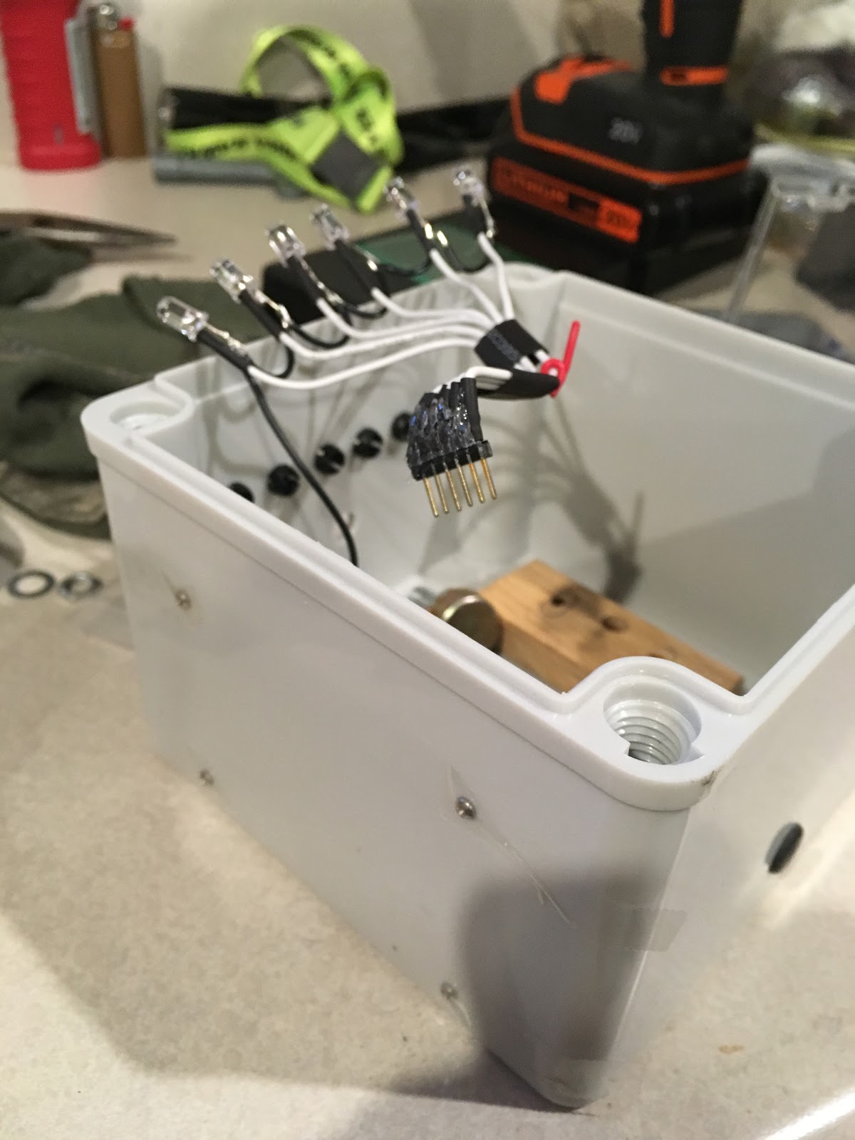


That turned out way longer of a blog post than I wanted, but hopefully it's useful.  Enjoy!


Friday, January 01, 2016

Getting Q-logic 2532/2562 (qla2xxx) and Linux-IO SCSI Target Working On RedHat/CentOS 6.7

Having oodles of enterprise shit at work makes me a bit spoiled, so it's nice to have some sliver of that at home. So one of the things I've wanted to do for some time now is have as-real-as-possible-to-me fibre channel SAN to work with at home but do it as minimalistic as possible.

However, a few things that won't be happening:
  1. Not buying and/or firing up any sort of rack-mount entry/mid/enterprise storage array at my place
  2. Making my eletric bill any more hefty from the amount of shit already running in my little datacenter close
  3. Have my wife draft up divorce papers for increasing the amount of space I'm already taking up with my stuff
A few things that are essential requirements (for me) for this:
  1. Reusing whatever hardware I have at my place and not buying anything of significant real expense
  2. Keep a small footprint (e.g. contained a mini-ATX case at most)
  3. Operational and managable on top of a full OS installation of CentOS/RHEL 6.x
So, the compromise to all of this is a cheap, Brocade fibre channel switch and using Linux-IO SCSI target package.

If you did any sort of high-level googling, you'd see that are successful and documented examples of this here, here and here with newer Linux distro's using Linux Kernel 3.x and Linux-IO 3.x packages.

Reason For Doing This


The reason I am doing this:
  • Because I need something to do on my 2015 holiday break from work
  • I stubbornly still run RHEL/CentOS 6.x distros because of my ever loving HATE of 'system-d'
  • RHEL/CentOS 6.x uses a stable but relic 2.6.x kernel --- which Q-Logic HBA fibre channel target mode is not merged into (obviously)
  • Even with a support Linux kernel that has Q-Logic HBA fibre channel support (3.x+), the Linux-IO packages for RHEL/CentOS 6.x (fcoe-target-utils) still won't work and you have to re-build those so it picks up the support in configFS under sysfs.  Since the tools are written in python, without digging into any code in 'targetcli' or 'rtslib', I'm leaning towards 'rtslib' being the outdated piece of fcoe-target-utils.
  • I'm sure one could have tracked and gathered a bunch of patches to see if it's possible to merge the tcm_qla2xxx + sysfs changes into the stock CentOS 6.7 (2.6.32-573.el6.x86_64) but it's just easier to re-compile the whole thing.

What Else this is useful for


There seems to be a lot of buzz off other people's blog posts about even folks using RHEL/CentOS 7.x not being able to get qla2xxx working.  Again, I lean on either parsing in 'targetcli' or 'rtslib' as a complete wild ass guess being the issue, since tcm_qla2xxx module is already pre-compiled and availbale with the stock kernels.

My advice would be just skip down to the latest-and-greatest Linux-IO compilation builds to get yourself going.

Install Needed Packages


Depending on how you baseline your RHEL/CentoOS 6.x installs, you'll definitely want to install these packages via 'yum' (and possibly more).  I'll order these by the groups of things you'll need the packages for just so it makes sense as far as what is depended for what.

For Linux kernel compiling:

$ yum install gcc ncurses-devel kernel-devel lsscsi patch git -y

For Linux-IO configshell, rtslib and targetcli latest rebuild:

$ yum install python-devel epydoc python-pyparsing python-configobj python-prettytable -y

Extra RPMs you will have to hand-install and can easily find on rpm.pbone.net for Linux-IO rebuild:

Build Linux 3.x Kernel (3.18.25)


This is a pretty clean-cut set of step(s) to get the kernel rebuilt and do the bare minimum tweak of enabling the build of the Q-logic TCM_QLA2XXX fabric module for Qlogic 2xxx series target mode HBAs:


Download and Unpack Linux Kernel Source


First step is to download and unpack the Linux kernel source:

$ wget --no-check-certificate https://cdn.kernel.org/pub/linux/kernel/v3.x/linux-3.18.25.tar.xz
$ tar zxvf linux-3.18.25.tar.xz


Copy Existing Kernel Configuration and Configure Kernel Build


Next is to copy over our latest stock kernel configuration for our CentOS as a starting configuration point so, if you want, you can build at a minimum what you have configured in your big, bloated distro kernel plus whatever you are going to enable.  Do note, there are numerous changes between 2.6 and any 3.x or 4.x kernel, so again, I'm not advocating this, but for the sake of 'getting shit done via blog directions', it'll do.

Let's change directory into the kernel source and run our ncurses text-based kernel configuration menu:

$ \cp /boot/config-2.6.32-573.el6.x86_64 /path/to/linux-3.18.25/.config
$ cd linux-3.18.25
$ make menuconfig

You'll want to, at a minimum, navigate to the following menu tree to enable Q-logic TCM_QLA2XXX fabric module for Qlogic 2xxx series target mode HBAs:

Location:
   -> Device Drivers                        
     -> SCSI device support           
       -> SCSI low-level drivers (SCSI_LOWLEVEL [=y])
         -> QLogic QLA2XXX Fibre Channel Support (SCSI_QLA_FC [=m])
          -> [m] TCM_QLA2XXX fabric module for Qlogic 2xxx series target mode HBAs

You can toggle on module (e.g. m) build by using your space-bar.  Then exit out of the menu's and save the configuration.

If you're super leery if you did the right thing or not, run this:

$ cat linux-3.18.25/.config | grep -q "CONFIG_TCM_QLA2XXX=m" && echo "enabled" || echo "not enabled"
enabled
$

...if you see 'not enabled' echo'd on the screen, you didn't get it enabled.  So you can either hand-edit that configuration line into '.config' or go back through ncurses menuconfig and re-enable it.  Either or will work.

Once your configuration is saved, we can build the linux kernel.


Build the Kernel and Modules


To build the kernel and it's accompanied modules, simply type:

$ make -j4 bzImage modules

...then go get some coffee.  If you compile with all the CentOS configured extra modules and add-in's you had with your stock os kernel, you're looking at just under one hour for a multi-threading build above.

Also, you'll definitely want to adjust '-j <n>' to your tastes; this runs automake with <n> threads.  Try to, at a minimum, make <n> equal to the number of cores you have on your system you are building on.


Install and Boot Into 3.x Kernel


After your kernel and modules build (successfully, I hope), it's time to install the kernel and the modules onto your system.  The linux kernel build strap scripts have come a LONG ways over the years and they work pretty flawelessly.


Add 'qla2xxx' target mode parameter for kernel module

This is an important step so prior to using the kernel build strap scripts for installing the kernel modules and invoking 'dracut', will automagically grab these options and incorporate them into your ramdisk (e.g. initrd).

Run the following command(s) to add the target mode enable options for the qla2xx fibre channel module:

$ echo "options qla2xxx qlini_mode=\"disabled\"" >> /etc/modprobe.d/qla2xxx.conf


Install Kernel, Modules and config


To install the kernel modules, do the following:

$ make modules_install

To install the kernel, do the following:

$ make install

This isn't a necessary step, but for the sake of making our custom kernel 'look and feel' the same, let's copy over the configuration as well to the /boot directory:

$ cp linux-3.18.25/.config /boot/config-3.18.25

Double-check the GRUB2 entries in '/etc/grub.conf' as well.  If you're super paranoid, you may also want to look at the contents of your in ramdisk (e.g. initrd) to make sure you got the 'qla2xxx' and 'tcm_qla2xxx' modules in there.


Reboot into New Kernel

Let's reboot your system:

$ init 6

We are going to assume you're going to leave your existing, distro-built kernel as 'default' and you'll manually select the 3.18.25 kernel from your GRUB menu.

If you don't and want to boot into this from the get-go without any intervention (e.g. maybe you're running a headless box like I am OR you're cocky as shit), just edit '/etc/grub.conf' and change the following line back to:

default=0

...so the bootloader defaults to the first-most kernel entry, which the linux kernel build strap scripts will put your new kernel at the top of the available kernels-to-boot list.

Do whatever you want to do.

Verify Kernel Installation

To do a quick kernel installation verification, obviously having the system back and booted is a probably the top indicator.

Next, let's verify the kernel we are booted into is, in fact, the one we built (sounds funny, but I have shot myself in the foot MANY times by overlooking that and skipping a few steps doing this by-the-cuff):

$ uname -r
3.18.25
$

Next, lets verify that our Q-logic module(s) can be loaded (assuming the card isn't plugged into any SAN fabric or have any existing storage attached/zoned to it).  You should see similar when running 'dmesg':

$ dmesg | grep -i qla
qla2xxx [0000:00:00.0]-0005: : QLogic Fibre Channel HBA Driver: 8.07.00.16-k.
qla2xxx [0000:02:00.0]-001d: : Found an ISP2532 irq 16 iobase 0xffffc90004afe000.
qla2xxx 0000:02:00.0: irq 26 for MSI/MSI-X
qla2xxx 0000:02:00.0: irq 27 for MSI/MSI-X
scsi host10: qla2xxx
qla2xxx [0000:02:00.0]-00fb:10: QLogic QLE2560 - PCI-Express Single Channel 8Gb Fibre Channel HBA.
qla2xxx [0000:02:00.0]-00fc:10: ISP2532: PCIe (5.0GT/s x8) @ 0000:02:00.0 hdma+ host#=10 fw=7.03.00 (90d5).
$

Lastly, lets load the target SCSI module we added and make sure that loads:

$ modprobe tcm_qla2xxx

Build the Latest Linux-IO Packages


Below are to-the-points steps to rebuild the latest and greatest Linux-IO packages you'll need since even after having the new kernel that supports Q-logic 256x target support, the current relic 'targetcli' package set still won't work.

Make sure 'fcoe-target-utils is Uninstalled


Before we go any further, let's make sure anything related to the stock distro 'fcoe-target-utils' is uninstalled and NOT on our system:

$ yum remove fcoe-target-utils python-rtslib python-configshell -y

Build and Install Configshell


To build and install the latest/greatest configshell, do the following command(s):

$ git clone https://github.com/Datera/configshell.git
$ cd configshell
$ make rpm
$ cd dist
$ rpm -ivh python-configshell-1.6.1~g020d540-1.el6.noarch.rpm

Build and Install RTSLib


To build and install the latest/greatest RTSLib, do the following command(s):

$ git clone https://github.com/Datera/rtslib.git
$ cd configshell
$ make rpm
$ cd dist
$ rpm -ivh python-rtslib-3.0.pre4.9~g6fd0bbf-1.el6.noarch.rpm

Build and Install TargetCLI


To build and install the latest/greatest TargetCLI, do the following command(s):

$ git clone https://github.com/Datera/targetcli.git
$ cd configshell
$ make rpm
$ cd dist
$ rpm -ivh targetcli-3.0.pre4.5~ga125182-1.el6.noarch.rpm

Verify 'targetcli' is working


Lastly, a simple verification and what will look different from using the 'fcoe-target-util' package targetcli command is the actual qla2xxx target config being loaded so you can set up your block storage backstores for export.  You'll also notice in the output of targetcli it references the rtslib build version we just build and installed via RPM, too:

$ targetcli
targetcli 3.0.pre4.5~ga125182 (rtslib 3.0.pre4.9~g6fd0bbf)
Copyright (c) 2011-2014 by Datera, Inc.
All rights reserved.

/> qla2xxx/ info
Fabric module name: qla2xxx
ConfigFS path: /sys/kernel/config/target/qla2xxx
Allowed WWNs list (free type): 21:00:00:24:xx:xx:xx:xx
Fabric module specfile: /var/target/fabric/qla2xxx.spec
Fabric module features: acls
Corresponding kernel module: tcm_qla2xxx
/> ls
o- / ............................................................................................................. [...]
  o- backstores .................................................................................................. [...]
  | o- fileio ....................................................................................... [0 Storage Object]
  | o- iblock ....................................................................................... [0 Storage Object]
  | o- pscsi ........................................................................................ [0 Storage Object]
  | o- rd_mcp ....................................................................................... [0 Storage Object]
  o- loopback .............................................................................................. [0 Targets]
  o- qla2xxx ............................................................................................... [0 Targets]
/>
That's it (in a big nutshell)! You should now be able to continue on setting up your block storage to front as a backstore from your newly set up fibre channel target.

Monday, August 31, 2015

Adding 'Hack' monospace font functionality into Spyder IDE in Fedora Core 21

As of late, a lot of the code I have been hacking out for just about anything has been straight, 100% Python.  With that, I've also ditched 'vi' + plugins and have grown extremely comfortable (and probably complacent?) using Spyder IDE GUI.  I never wanted to be GUI dependent (again) but I am, so whatever.  I deal with it.

But, recently, I saw a post on arstechnica.com touting the coolness of Hack, an open-source monospace font marketed towards the code slingers of the world.

I undoubtedly get tired of using of the defacto DejaVu and Liberation monospace fonts and decided to give this a shot.  And quite honestly, even though it's subtle, I really like it.

Characters of note:  I don't notice the lowercase-L vs. the numeral 1 as much as I do the zero vs. uppercase-O and lowercase-I curvature.

Font sizes:  I think my favorite font size is 9px or 11px (11px especially if I've been staring at my monitor for more than 4 hour straight with contacts in to boot!)

The overall font character scheme also seems a bit more compressed as well, which is nice so I 'feel' like I'm getting more width real-estate.  Case in point:  take it for what it's worth.

Even though this is a less traditional and definitely 'non-distro' way to add an overall font to your OS, I think it gives most people the flexibility enough to give it a shot themselves with as minimal overhead as possible, especially if you want it 'long-term' and want to put it in the same place as your other distro fonts via package management without creating a distro package for it.

Here's how to make the 'Hack' monospace font accessible in Spyder IDE under Fedora (or any other RHEL based OS for that matter).

If you really want to get technical and overview-ish, I guess this would be a good way to hack-and-slash 'any' font you want to Spyder, monospace or not.

Download and Unzip 'Hack' Font from SourceFoundary

Go to Hack's SourceFoundary site and download the True-Type font .zip archive.

Once you have downloaded the 'Hack' fonts, simply unzip them wherever you want:

$ cd /path/to/hack/fonts/
$ unzip Hack-v2_010-ttf.zip
unzip Hack-v2_010-ttf.zip 
Archive:  Hack-v2_010-ttf.zip
  inflating: Hack-Bold.ttf           
  inflating: Hack-BoldOblique.ttf    
  inflating: Hack-Regular.ttf        
  inflating: Hack-RegularOblique.ttf
$

Add 'Hack' font into to your OS

Adding the Hack monospace font (this way) is pretty trivial.  The key point here is to know the top-level path where your Linux distro stashes it's fonts.  For a font like this that I really want to use long-term, I think this is a better solution than putting it in ~/.fonts/  or equivalent. I'm also going to assume you have proper privileges to do all these command(s) or know how to obtain it (e.g. NOT prefacing the sudo command to obvious root-level stuff)
  • Create a new directory for the 'Hack' font in your Linux distro's top-level system font path
  • $ mkdir /usr/share/fonts/hack
    
  • Copy fonts over
  • $ cp -a /path/to/hack/fonts/Hack-*.ttf /usr/share/fonts/hack/
    
  • Make sure permissions + ownership are sane on your font directory and fonts
  • $ chown -R root:root /usr/share/fonts/hack && chmod 755 /usr/share/fonts/hack
Changes to Spyder IDE

I'm using Spyder IDE v2.2.4, so YMMV if you're using another version.  I didn't go scout all this out, but it's pretty self-explanatory.

Spyder IDE has a default, hard-coded list of approve and available monospace fonts that are defacto standards.  All you have to do is alter the list data structure defining the list of monospace fonts in spyderlib.

To do this, you'll want to look for the following line of code in /usr/lib/python2.7/site-packages/spyderlib/config.py module:

MONOSPACE = ['Monospace', 'DejaVu Sans Mono', 'Consolas', 'Monaco',
                'Bitstream Vera Sans Mono', 'Andale Mono', 'Liberation Mono',
                'Courier New', 'Courier', 'monospace', 'Fixed', 'Terminal']

...and add in the 'Hack' fonts into the MONOSPACE list structure so it looks something like this:

MONOSPACE = ['Monospace', 'DejaVu Sans Mono', 'Consolas', 'Monaco',
               'Bitstream Vera Sans Mono', 'Andale Mono', 'Liberation Mono',
               'Courier New', 'Courier', 'monospace', 'Fixed', 'Terminal',
               'Hack-Regular', 'Hack-RegularOblique.ttf', 'Hack-Bold.ttf',
               'Hack-BoldOblique.ttf']

NOTE:  There are several 'config.py' modules in Spyder IDE, so if you're really confused at this point, just do a case-insensitive recursive grep (e.g.  grep -i -R "MONOSPACE" /path/to/spyderide/site-package/install) and find the right one to edit.

Restart Spyder IDE and Choose 'Hack' as your Font

If you still have Spyder IDE running, close it and re-open it.

Then on Sypder's top menu bar, you'll want to navigate to 'Tools > Preferences', then select the 'Editor' option on the left-hand side.  Now, if you select the 'font' drop-down menu, you should see 'Hack' available for your choosing:


You can now click 'Apply' and watch all those wonderful tabs of 'code' change over to using 'Hack'.

If you also want your Python console in Spyder to use this font as well, just select 'Console' and change it there, too.

Before-and-After of Hack vs. DejaVu Sans

Here's a couple of quick screenshots put in extra-large to show the differences of Hack vs. DejaVu Sans out-of-the-box Spyder IDE font:

DejaVu Sans - Normal - 9px

Hack - Normal - 9px


Now as much as I'd want to package this into an RPM for my own sake in case some update comes about, that would just be more work than it's worth.

Enjoy!

Sunday, November 25, 2012

Motorola Oncore UT+ Interface and PPS Breakout Board + Schematics

I've been a long dabbler of all things 'network time' related for 5+ years now and do maintain a fair number of stratum-1 time sources for myself (two Motorola Oncore UT+, one Trimble Thunderbolt and soon-to-be WWVB). I shouldn't be that selfish and really make them a part of the NTP public pool; we'll see.
Out of the several hobbyist-affordable time sources to obtain (Garmins or any NMEA-output), I do think the Motorola Oncore UT modules are pretty top-notch in terms of reliability, stability and performance. I think it provides just the right amount of challenge and barrier-to-entry for anyone who wants to dabble in EE and do some TTL-to-RS232 logic shifting to get one of these to work.

Reasoning Behind This

1) Arrangement and un-honkify my setup: To nicely arrange the Motorola Oncore module with a MAX232 and a battery for backup onto some sort of prototype perf board. For the LONGEST time (3+ years), I had an individual TTL-to-RS232 DB9 breakout screwed to some wood, and used a DB9-serial ribbon cable (since the Motorola Oncoreh has a 10-pin male header and the DB9-serial conveniently has a 10-pin female socket + ribbon). I'm no engineer, but I like to pretend to be one on my spare time (and at work when I'm allowed to) but I thought it was about time to make my stuff look a little bit more professional and less honky.
2) No onboard battery for almanac storing with power-loss: My UT+ modules do NOT come with an onboard battery, thus every time I'd lose power, the cold-start time on the GPS was enough to piss me off from time to time. I used to have a UPS but kW usage over time really added unnecessary 'cost' to my electric bill to the point where I could really live without forking over several hundreds of dollars to 'the man' a year for the few times I lose power intermittently.
3) Constant falseticker issues with current hardware setup and PPS from Motorola: For whatever reason (and I think partly due to newer ntpd versions, see this post) ntpd would label my PPS timesource as a falseticker all the time and it was frustrating. I didn't want to do some configuration hack and force truechimer status with 'true' in the ntp.conf config. What I was currently doing is sending the 1PPS TTL signal straight to DB-9 Pin 1 (carrier Detect) on the assumption that RS-232 logic is 3-24v, so clearly +5v TTL would 'barely' fall into it that logic path, but would. After some forum posting, I decided to move the 1PPS signal through the MAX232 TTL-to-RS232 shifter as well and my current circuit only took two inputs; one for Rx and Tx. So a redesign was needed.
4) Get the RS232 DB-9 serial output and antenna to be in the same location: Right now I plug my DB-9 serial cable in on the right side then the antenna is on the opposite side so it makes positioning this thing in my closet hard with my crappy setup.

The 'Solution' (so far)


This certainly isn't complicated at all. Biggest time waster on this is:
1) Soldering time --- take a while to solder all that together when it's thru-hole.
2) DESIGN!!!: Because I wanted this to 'snap' together and sit on the underside of the UT module, I had to really think about this. I certainly didn't plan it out as nice as I turned out (I think). Here's another few pictures of me putting it together, along with the final product, and how it fits together underneath the Motorola Oncore module:

Parts List

Since I did my schematic with Digikey's scheme-it, I was able to make a nice bill of materials in case someone else wants to dupe this. I'm not endorsing Digikey, but you'll be able to see what I used; I had all these parts on hand from years of accumulation.

Object  Name            Value           Digikey Part #
R1      RESISTOR        1k8              CF14JT1K80CT-ND
R3      RESISTOR        470k             CF12JT470KCT-ND
R4      RESISTOR        330k             CF18JT330KCT-ND
J2      2X5                              952-1924-ND
J3      9-PIN,          FEMALE           A32510-ND
IC1     IC              MAX232CPE        MAX232CPE-ND
C1      NON             1uf              P4537TB-ND
C2      NON             1uf              P4537TB-ND
BT1     BATTERY         HOLDER CR2032    BU2032SM-HD-GCT-ND
J4      1X2                              TMS-104-02-S-S-RA-ND
C3      NON             1uf              P4537TB-ND
C4      NON             1uf              P4537TB-ND
R2      RESISTOR        1k8              CF14JT1K80CT-ND
L1      LED             Red              751-1089-ND
L2      LED             Green            51-1105-ND
Get whatever type of thru-hole prototype perf board you want; I had some leftover stock I picked up from Radioshack a long time ago.

Improvements To Add

1) Put some inline diodes for some circuit protection along with a 5v voltage regulator --- I'm under some wild assumptions that I'm the only one who will ever use this and always apply 5v DC supply to it.
2) Still work on that battery indicator just because after I stuff this up in my closet, it gets easily forgotten. I stumbled across this for a 3v low battery flasher using a Panasonic MN13811-G, but that MN13811 was pretty hard to find anywhere (digikey, mouser, etc.)
3) Get it off the wood 1x4 mount and get a proper project box to enclose this.

NTPd info

Here's a snapshot of my tuned ntp.conf for the Motorla Oncore UT's (in case you need a jumpstart on it):

enable pps 
pps /dev/oncore.pps.0 hardpps

# Oncore Motorola UT+
server 127.127.30.0 minpoll 6 prefer
fudge 127.127.30.0 time1 0.1988

# Oncore Motorola UT+ 1PPS on DCD
server 127.127.22.0 minpoll 6 prefer
fudge 127.127.22.0 time1 0.39726

tos mindist 0.010
Here's a look at my peers listing:

$ ntpq -p
remote           refid   st t when poll reach   delay   offset  jitter
======================================================================
LOCAL(0)        .LOCL.   8 l  486   64  200    0.000    0.000   0.000
*GPS_ONCORE(0)   .GPS.   0 l    3   16  377    0.000    0.010   0.003
oPPS(0)          .PPS.   0 l   34   64  377    0.000    0.099   0.133
$

Resources

A few sites of interest I referenced and used for the idea:
1) TAPR Motorola Oncore Interface SemiKit (http://www.tapr.org/gps_vpib.html): I'm sure I've looked at this while re-referencing the Motorola Oncore manuals from here, but this is EXACTLY what I wanted to do. However, I'm not going to pay to get boards made, nor do I want to have an all-fitting Motorola Oncore interface board; I just have UT's.
2) Simple low battery indicators (http://kyorune.com/modding/article.php?id=55): This is very, very barebones. However, it gave me a good opportunity to do some testing, even though I kind of knew a head of time this was going to be too expensive milli-amp wise on the battery to even make it useful. The Motorola draws in micro-amps, so the the added value of an LED drawing at milli-amps just makes no sense.